Friday 31 December 2010

Hazard Warning Lights

One thing that always makes me nervous is stopping on the side of the road - I like to be able to switch on hazard warning lights even if I jump out to post a letter, so when Practical Classics published in November 2010 a DIY hazard warning system I decided to set to it.

Now it is true that you can probably buy ready made hazard warning systems on eBay for a similar price to the DIY version, but it just isn't half as much fun!

Here is the list of parts that the Practical Classics system requires:


and also the circuit diagram:


One thing that is certainly different about this version, is that it can be used on anything from 6 volt to 24 volt vehicles thanks to the solid state voltage regulator that pumps out an even 6 volts regardless of the input voltage. This voltage is required to drive the 6 volt relay circuit that is used to switch the battery voltage to the indicators.

Another difference is the inbuilt multi-colour LED that is used to indicate a blown bulb through the use of reed switches. I didn't want this functionality - after all, in our old vehicles we know when a bulb has blown - our indicators stop working !! So I stopped at the output from the relays and connected into the indicators.

One problem with the write up in the magazine is that they left one very important point out, or rather didn't explain it properly. The timing mechanism that controls the flash rate of the hazard warning system is controlled by the BLUE LED - so you need to make sure that you buy a flashing LED. This does limit the amount of control that you have over the flash rate, but I reckon mine is flashing at roughly 2 flashes per second which is the maximum allowed in the regulations.

I copied the diagram out on a piece of squared paper so that I could mimick the copper strips on a piece of strip-board and created my own version of the circuit diagram with markings for where I would need to cut the copper strip, and where to solder on the components.

Here is my completed unit:


So that I could test it out, I found a few indicator units for my Rover P6 and connected it up - here's a video....

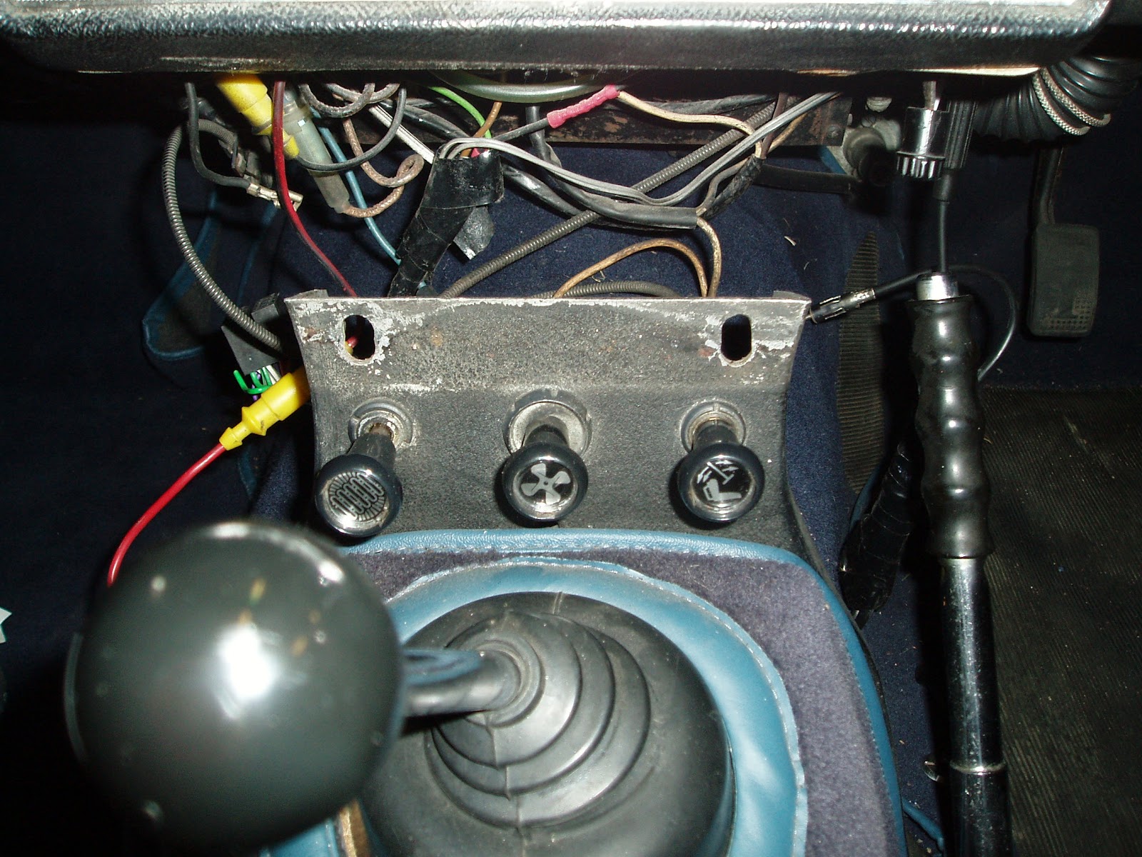
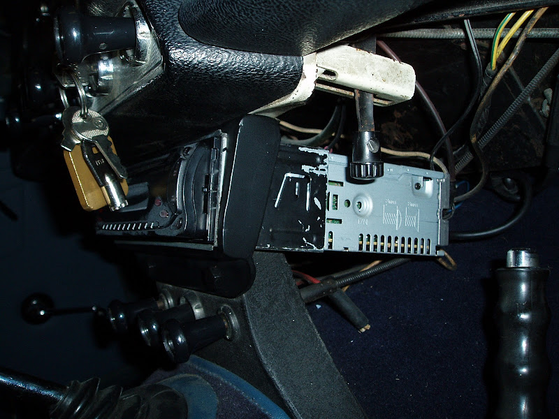
I fitted it under the dashboard fastened to the steering column. I didn't want it to be a permanent fixture. Also, tucked up out of the way, the MOT tester can't see it and therefore never tests for it. I also don't like making permanent holes in the car if there is no need to do so.


Please feel free to comment on my blog by clicking on the "comments" link below.

Monday 14 June 2010

Scuttle Shake and the "Radio Plate"

When I bought Tina, the previous owner did tell me that I needed to weld this plate up ......... I finally got round to it. I'd been putting it off because I'd never welded before. I'd bought myself a MIG welder off eBay a couple of months ago, but never used it.....

OK so first what is scuttle shake? According to Wikipedia.....

"Scuttle shake (sometimes called cowl shake in the US) is the term used for the phenomenon experienced in many convertible or open top automobiles, where due to lower structural rigidity caused by the lack of a roof, the middle section of the chassis flexes, causing the bulkhead in front of the passenger compartment to move and vibrate when the vehicle is subject to uneven road surfaces. Passengers feel it as a noticeable vibration and shudder."

In the TR4, one of the areas where some bolting together of panels is done to increase rigidity is in the centre section between the transmission tunnel and the dashboard in this gap here:


You can see here the two holes above the three heater switches where the plate would bolt to, there are two matching holes above in the dashboard out of sight.

I've no idea what this plate was used for originally back in the 60's, (besides rigidity) but I have seen other cars with a bank of 'add on' switches and mine has a radio - so perhaps it was originally a blank plate.

I guess they'd have coped with old 60s/70s radios, as they had a small aperture, the radio went behind the plate and the face and knobs were popped on the front. Modern radios however have a large aperture, and this had been cut into my plate.......


The resulting scuttle shake was too much for the thin sides to take and they broke. I needed to weld this up.

First problem, I've zero experience of welding, and I need to be able to hold this plate firmly and in the position to be welded while keeping the correct shape. I wanted a jig.


Yes I know it's wood, and welding might burn it! but I decided to take the chance. Notice how the top of the jig slopes back, the radio plate isn't exactly flat and so not that easy to just hold still. This made more sense. And although it's wood, it did survive!


It holds it still perfectly - now to sand off the paint and get welding!


Ta da! not a bad job - after getting the flap disc on it and grinding off the weld! Yes this really was my first attempt at welding, but then as it's 3mm steel, I thought there was very little chance of me burning a hole in it, so worth a go.
the whole structure needed strengthening though, I went off round the Yellow Pages finding steel fabricators and scrounged some 3mm plate and also some 18 guage steel (for practicing proper welding). I wanted to box in each end of this plate to make it much stronger.


That's better, much harder job for me too, but I was just starting to get better by the time I'd finished. And from the back.....


Not too much pidgeon poo there! I needed to file down some of the welds to enable the radio to pass through the gap, but no need to go to town tidying them up, they'll add to the strength and be completely hidden. Just gotta paint it up now and refit to the car.


Great job, car handling transformed, let's hope this time it lasts!


Please feel free to comment on my blog by clicking on the "comments" link below.

Monday 31 May 2010

Headlamp Aim? More like where is it aiming!

Tina was MOT'd when I collected her, and I know there was an issue with the headlamp aim on the offside but assumed that it was fixed.

When I got her home, parked in front of the garage and put the lights on. Strangely the off side was high, then when I put the main beam on, what you'd normally expect is that the main beam is higher than the dip beam. On the offside, I had the main beam lower than the dip beam - something obviously wrong.

I took the sealed beam out and looked at the wiring........
Also found this handy link with the definition of the connectors on the sealed beam unit:
http://freespace.virgin.net/tommy.sandham/lampfittings.htm

I've reproduced the information here:


I had according to the diagram:
1 = Blue/red
2 = Black
3 = Blue/White

or in other words:
The dip beam wire was connected to the main beam terminal
The main beam wire was connected to the earth terminal
The earth wire was connected to the dip beam terminal

No wonder it didn't work properly! In fact I'm surprised it worked at all.

Wait 'till I have a word with the seller, a bit of teasing is in order!


Please feel free to comment on my blog by clicking on the "comments" link below.

Sunday 23 May 2010

Air Horns ..... on a TR?

Tina came with musical Air Horns and a very weedy main horn. I couldn't get the air horns to work, so they had to be removed from the car and stripped down.


You can see here with the top of the air compressor removed, the slotted metal disc. It is this disc that plays the 'music'. As each slot goes past the outlet of one of the three air horns, air is delivered to that horn for the duration that it takes the slot to pass by. If we look under the disc.......


Here you can see the cogs that will turn the slotted disc. The problem with this compressor is that it was dry. So I covered the components in oil. There are also four holes round the edge for screwing the top on the compressor, but only 3 screws, one of them is an oil feed to the pump, so when it is in the car, you can take a small screw out, add oil, and put the screw back.
Now with the compressor oiled, and connected to my power station, it would only blow a single tone - that is all 3 air horns at the same time. As far as I could tell the slotted disc would be moving, but it wasn't 'playing'...so the air must be going over the  top of the slotted disc???
After a day or two at work, daydreaming in a meeting, I had one of those Eureka moments. Look at the top of the compressor and notice the red 'tag' sticking out at the 9 O'clock position. I'd always wondered what this was for, it was connected up in the car like this:


The blue wire on the left is jumpered from the live feed to the compressor. The yellow wire goes to a knob on the dashboard to put the wire to earth when pulled.
Inside the top of the compressor is an electro-magnet. When you connect the yellow wire to ground (pulling the dashboard knob) it engergises the coil and operates the magnet. This pulls the slotted metal disc to the top of the air compressor and ensures that the air does not escape, the rotating disc then plays the tune!
So that explains why she was fitted with air horns, when you're low to the ground, you need to be seen - and heard! the music is just an addition, but the triple horn blast will make sure your heard!

Here it is being bench tested:

All working again - now just need to paint them up and tidy up the wiring - I need a new relay, the original relay looks like it was used to power somthing out of Noah's Ark!!


Please feel free to comment on my blog by clicking on the "comments" link below.

Tuesday 13 April 2010

Tina - The Triumph TR4

Bought on 13 April 2010


She is a 1965 TR4 in Wedgewood blue
Full body off restoration and engine rebuilt in 1987 and only about 36,000 miles since then.
Resprayed/Carpetted/Upholstered in very recent years
Chrome Wire Wheels
Surrey Top (Rear Windscreen, Hard Roof and Soft Roof)
Bespoke Wooden dashboard and steering wheel
Overdrive gearbox.

The "First" owner on the V5 (because the DVLA can trace earlier than the mid 70's) owned the car from 1974 to 2003, in that time....
1974 Acquired at approximately 80,000 miles as a full convertable.
1987 At approximately 107,000 miles. Full body off chassis restoration. New floors, inner wings, wings, aluminium boot, rebuilt suspension, rebuilt engine and recored radiator.
1987 Moved to Australia, and took the car with him and registered in Adelaide as TRIU 65.
1989 Moved back to the UK and took on the original registration CFU 328 C
1992 Converted to Surrey Top
2002 Converted to SUs as per TR4A instead of Strombergs