Friday 24 June 2011

Finding Top Dead Centre

When I bought Tina, she'd already had a thin fan belt conversion. One of the changes for this, is of course to change the crankshaft pulley - which contains the timing marks.

Reading up on how to check/set the timing, I was amazed to find out that the only mark on the crankshaft pulley is Top Dead Centre, and that the timing MUST be set statically. This is because the mechanical advance starts at about 450 RPM, so even when the car is idling at about 800 RPM, the mechanical advance has already kicked in. The stock workshop manual setting is for 4 degrees BTDC and to achieve that you have to set the ignition to Top Dead Centre, and then turn the vernier adjuster on the distributor to advance the timing by 4 degrees.

I didn't know what Tina's timing was set at, even if I looked using the light bulb across the distributor method, all I would see is that the timing was somewhere before TDC, but not actually know where. In addition, because the crankshaft pulley had been changed, I wasn't sure I believed that the TDC mark was actually in the right place. I needed a method of accurately finding TDC and then also the number of degrees BTDC.

I did a bit of googling on this subject and decided to ignore the "pencil down the spark plug hole" and "whistles" as I'm not convinced that these methods are any good. During the crankshaft travel over the Top Dead Centre, there will be a degree or two where the piston is not conceivably moving at all - because the crank is moving virtually horizontally at that point. I did stumble on the following method which I am convinced is about as accurate as I can get, and as accurate as I need to be.

First, I needed an old spark plug - I'd got plenty from my Rover P6, so I set about destroying it. It takes some doing, but you need to remove all of the ceramic insulator and the electrode, then with some silicone "bath sealant", glue/seal in one end of a 2 - 3 foot length of clear windscreen washer hose and leave to dry.


Remove Number 1 spark plug and the distributor cap. Rotate the engine by hand until the rotor arm is approaching the "No 1" position so that the No. 1 piston is on the compression stroke. Insert the home made plug with the hose attached and tighten, dip the other end in a small pot of oil. Mark the hose about 2 inches higher then the surface of the oil in the pot.

Continue to turn the engine by hand, as the piston continues on the compression stroke, bubbles will be blown through the hose/oil, but as the piston commences the power stroke, oil will start to be sucked up the hose. As soon as it reaches your mark on the hose, stop and mark the crankshaft pulley.
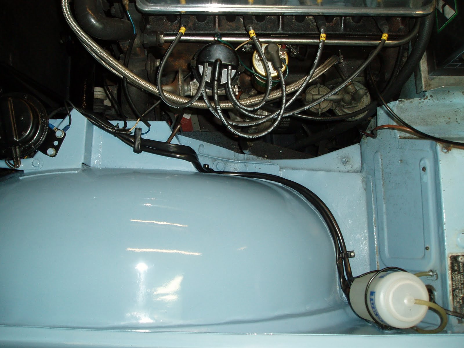
Here's a photo of the oil being sucked up - You can see that I sucked the oil up a long way past my mark, but that was just for the photo - the mark is down inside the pot and wasn't sure if it would show up very well.

Now turn the engine slowly backwards, as the piston reverses the power stroke, the oil is forced out of the hose, as the piston reverses the compression stroke, oil is pulled back up the tube. Again when the oil level reaches the mark, stop and mark the crankshaft pulley.
Perform this procedure a couple more times to double check your markings, when you are happy, Top Dead Centre is exactly inbetween your two marks on the crankshaft pulley.

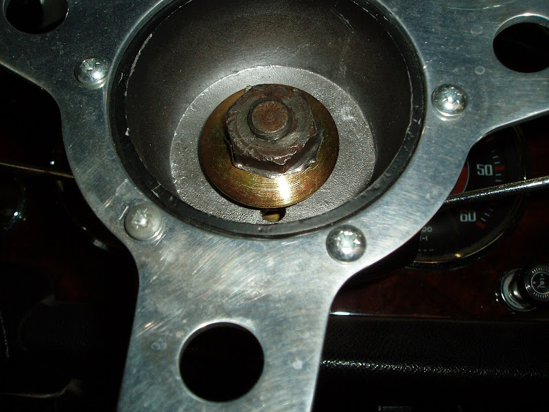
Here are my results, showing my two black marks and the original TDC notch in the Crankshaft pulley.


On this one, I have used a pair of dividers to measure the distance between my two marks, halved it, and then put a white mark on my real Top Dead Centre. You can see that there is a difference between my measured TDC and the actual mark on the crankshaft pulley. It does look like my white mark is not exactly in the centre, but that is due to the angle of the photograph and the curvature of the pulley.


I took a pair of "outside caliper" dividers to measure the diameter of the crankshaft pulley which I measured as 139 mm. By using some basic maths, PI*diameter = circumference of the crankshaft pulley. Dividing the circumference by 360 (degrees in a circle) will give me the distance in millimetres between degrees.

PI x 139 = 436.7 - Circumference is 436.7mm

436.7 / 360 = 1.2 - 1.2mm of the circumference per degree

Using dividers to measure the distance from the TDC notch in the pulley to my white mark showed that the distance between the two is 3.5mm.

3.5 / 1.2 =2.9 degrees

So the TDC notch is approximately 3 degrees After Top Dead Centre !!

I connected up an analogue voltmeter to the distributor and turned the engine until the points opened to check what the timing actually was set at and using dividers, measured the distance from the white TDC mark to the engine pointer. Using the same maths as above, my timing is set at about 6 degrees BTDC, rather more than the 4 prescribed by Triumph, but she behaves very well and never pinks so I'm leaving well alone. Interestingly, if she was originally setup using the TDC notch on the flywheel, then she'd be believed to be running at about 9 degrees BTDC !!


Please feel free to comment on my blog by clicking on the "comments" link below.

Wednesday 22 June 2011

New Fuse Box and Relays

I was never very happy with the wiring in Tina. Much of it looked hap-hazard and suffered from what many cars of this age suffer from - loads of redundant wiring from additions made over the years, and then when those additions were removed, the wiring left behind. When I first bought her, I removed yards and yards of wire that was doing absolutely nothing.

While I was painting the engine bay, I wanted to sort out what was left. For example, I had an electric fan that was connected to the main fuse box (powered from the ignition switch) and would be pulling about 10 Amps. It was connected to the 35 Amp Lucas fuse, and then passed through two in-line 25 Amp fuses before reaching the fan. The fan thermo-switch was controlled off a sensor in the top hose, which I later converted to a thermo switch in the bottom hose.

I'd also heard stories from TR Register members about the lighting switch being a weak point (perhaps justified after 46 years) and that relays in the lighting circuit would be a worthwhile addition - would certainly save on the cost of repairs after a dashboard fire! I already had one modern relay in the engine bay to supply power to the air horns and wanted to hide it.

I'm also thinking of taking the load off the ignition switch for all accessories

Here is a picture of the wiring mess in the engine bay before I started.


I didn't want to add any relays into the engine bay, I wanted it to look reasonably original, and rather than use the old fashioned Lucas 6RA relays, I wanted to use the modern variety which are much smaller and therefore easier to hide somewhere. I obtained  second hand Lucas fusebox from the 60s/70s era that would hold 4 fuses (it came off a Rover P6) and decided to fit them into the passenger footwell.
I made a bracket out of a piece of steel, bent it in the vice to provide the right shape, and drilled 5 holes to accept a bank of five relays. I figure I'm going to use:
1. Air Horns
2. Main Beam
3. Dipped Beam
4. Accessory feed (take the load off the ignition switch)
5. Spare


I ran a brown wire (33 Amp) from the A1 terminal on the voltage regulator to the fuse box. The A1 terminal is the feed to the ignition switch, so this is permenantly live and is equivalent to taking the power off the back of the ignition switch. This feed will provide power to the fuse box for all permenantly live requirements (e.g. horn, electric fan).

I decided that as the headlamps were never originally fused, I would do the same and created a junction with bullet connectors to Tee off the power to the headlamps relays.

I bought plenty of wiring of the right colours from Vehicle Wiring Products and some PVC sleeving to thread the new wiring through so that it looked like part of the loom instead of creating another mess of exposed wiring running the length of the engine bay.

To connect the headlamps/main beam to the relays, this could be done in two ways - either find the wiring inside the car somewhere near the dip switch, or from the front of the car where the power wire splits into two to feed both headlamps. I decided to do the latter, which also seemed to be the common junction point for others that have done the same thing on the TR Register forum. I fed one PVC sleeve with 4 wires for the headlamps. Two of these would be an extension of the original power wires (main beam and dip beam) which would now form the switch power at the relay, and 2 wires which would now actually supply the power from the relay back to the main and dip beam.

To connect the electric fan and the air horns, I ran another 3 cables through another PVC sleeve. These were power to the air horns, "music" on/off wire for the air horns and the electric fan, each went to a fuse in the fuse box.


The PVC sleeves and their wires was pushed through the grommet on the nearside that also has the wiper motor wiring and connected up to the relays. Yes it does look like a bit of a spagetti mess, but I needed the wire tails to be long enough for me to reach into the passenger footwell with my crimpers - child labour is outlawed you know!


So after all that, I now have additional wiring in the engine bay that is very tidy, only one fuse for the electric fan instead of 3, and a much safer light switch on the dashboard. The new fuse box is now supplying the air horns, electric fan and my hazard warning lights (see other post)

With the help of a small block of wood and a piece of hardboard cut to shape to make a false bottom to the footwell, I only lose about 3 inches from the depth of the passenger footwell and everything is nicely hidden.


My next addition will be to take another live feed to a new relay which will be activated by a power feed from the auxillary power terminal on the ignition switch. The resulting output from the relay will feed the last 2 fuses on my new fuse box, and also fuse A3-A4 on the original fusebox in the engine bay. This will remove all current from the ignition switch and increase safety on the old dashboard switches. But I need to buy another relay for that one and so haven't got around to it yet. Once this modification is completed, I will alter the wiring for the radio and the air horns to use the auxiliary power, and move the 12 volt power socket from the original fuse box to the new one.

It's all very well making all these changes to the wiring loom, but unless it's all written down, you can guarentee that in a year or two, I'll have forgotten what I did. So I modified the original wiring diagram to reflect all these changes. All live additions are in blue, planned but not implemented changes are in green and wiring that will be decomissioned after changes are in red.


Please feel free to comment on my blog by clicking on the "comments" link below.

Friday 17 June 2011

Painting the Engine Bay

It all started with Tina needing a coolant change. I didn't know when it was last changed as I've only had the car for 12 months, but classics need the old fashioned blue ethylene glycol based antifreeze which only lasts for 2 years, so it was time.

I thought that while I was at it, I'd take the radiator out and give it a back flush, and while it was out I'd paint it.

While the radiator's out, I might as well paint the horns too.

...and while I was at it, I'd change from the crap aftermarket overflow bottle for the pukka TR4A version.

The existing aftermarket overflow bottle was on the near side and the air-horns on the offside. The correct overflow bottle has to sit on the offside, so I also had to relocate the air horns.

Here's a few snaps of the engine bay before hand......


It was when I got the radiator out that I noticed how bad the paintwork was at the front end of the car, so no option but to sand it down, jenolite the rusty areas and respray.

It took forever to mask off the engine, especially taping up all those wires. Then I gave it a good spraying with the colour matched paint I had made up at Sayers in Northampton.


Looks even better when the masking was removed. However this then showed up just how bad some of the black metalwork (radiator tie bars and chassis) was, so this needed to be hamerited / undersealed to make it look just as good as the rest of the engine bay.


Next I moved the air horn compressor to the near side. I had to drill two new holes to mount it, and I closed off the old holes on the offside with blanking grommets.


I bent the air horn mounting bracket to suit the near side and then discovered that it was 7mm too short! So had to cut it and weld in a fillet. Although it was painted black before, I decided it would be best in wedgewood blue


Next to fit the coolant bottle on the offside. The Moss kit came with a bracket .... that didn't fit. Presumably it would fit a TR4A but on my TR4 there was not enough room and fouled either the bodywork or the steering rack - and then didn't allow enough room to drop the bottle in it. So, cutting a piece off the mounting lug and drilling a new hole, it fitted onto the hole on the radiator bracket in just the right spot. The kit came with some rigid plastic tubing that needed heating with a hair dryer to make it pliable enough to push onto the radiator overflow pipe.

These overflow bottles are not like the later cars expansion tank. The expansion tank principle works by having an enclosed radiator - by blanking off the filler with a non pressure cap, and having the pressure cap on the expansion bottle.

The overflow bottle in this case simply catches the water overflow when the water heats up and spills out under pressure. When the water cools down, water is sucked back into the radiator because there is a second valve inside the radiator cap that allows the water to return. The effect of the overflow bottle versus the expansion tank is identical. Just a different way of achieving the same thing.

Nearly all finished...


A couple of weeks later, the underside of the bonnet was dirty and marked, many of which would not sand out, so that too had to be painted to match the rest of the engine bay.
Here is the finished bonnet too.


Please feel free to comment on my blog by clicking on the "comments" link below.

Sunday 20 February 2011

Making the Standard Horn Work

I've seen this on several TRs that I've looked at, particularly those that I was looking at when searching to buy. After many years, and many steering wheel changes, the horn has been relocated....sometimes to some crappy looking aftermarket button on the dashboard, spoiling a nice wooden dashboard!!

I've seen very few TR4s with the original steering wheel, by now many have been changed to a Mota-lita or Mountney.

In a previous blog entry, I described the Stebel Air Horns that had been installed on Tina back in the early 70's and how these needed to be recommissioned and also rewired. The horn in Tina's case had been moved to a lever underneath the dashboard - so at least nothing was defaced.

I want to get the original horns working through the button in the centre of the Mountney steering wheel. After all, sometimes your reaction on needing the horn is to hit the wheel, not fumble under the dash - we'll save that under-dash switch for scaring people out of their underpants with a blast of the Air Horns!!!

So, How does the horn work...... Here is the steering wheel.


The centre of the wheel is the horn push, nice one this with the Triumph logo on it. This horn push will lever off with careful use of a screwdriver.....


That looks odd - doesn't look like there is anything there to make a connection with the horn... just a great big nut (which is too big for my socket sets) and a fat washer.. hmmmm......

Look what I found under the washer.......


A HOLE!!!
Yes, this is what I was looking for. Through the hole is a "Slip Ring" and the component that is missing is called a "Horn Brush" it is a spring loaded copper rod that sits between the slip ring and the horn push. Basically, as you turn the steering wheel the horn brush is fixed in contact with the horn push and slides around the slip ring thereby keeping both items in contact.
Inside the steering column, the horn is directly connected to the slip ring, the slip ring connects to the horn brush, the horn brush connects to the horn push on the steering wheel. Lets have another look at the horn push.....


I think (but not sure) that some horn push switches have a big contact in the middle, then as you push the horn you push the centre contact down to make contact with the horn brush. Clearly not the case here. What you can't see here is that on one section of the edge of this button is a metal plate to make contact with the steering column boss when it's inserted into the wheel. A quick check with an electrical meter showed that this horn push was an internal switch. Pressing the horn push made the electrical contact between the metal plate on the edge and the centre contact that you can see in the photo. So, that centre contact actually needs to be connected to the horn brush somehow.

So there we have it, that's how it works so how do we test it ........ push a screwdriver down the hole! Err, that didn't work, time to look at the wiring.

Of the wires entering the steering column for the horn, only the live feed enters, there is no earth. The horn earths through the steering column itself, down to the steering rack and onto the chassis. To confirm this I connected a test wire to earth, touched the steering column as it passes through the bulkhead in the engine bay, pushed a screwdriver down the hole in the steering wheel boss to earth the slip ring to the boss and ...... PARP! It works, we have an earth fault!

After numerous checks down the steering column, I believe I have two faults. This is one.


If you look carefully, the bit circled in red is an earth strap. it connects the earth in the steering column through the rubber flexible coupling to the next section of the steering column. This earth strap has broken and is no longer connected to the bolt head just above it. I will need to fix this, the easiest way will probably involve two ring connectors and a new wire through the centre of the coupling to connect to the clamping bolts. Replacing the earth strap properly will involve removing the carburettors and will be a much bigger job.

The final problem, I think is due the steering column having probably been replaced at some time......


Here you can see that the splines on the steering column are all nice and black. I believe that the black paint is insulating the column from the clamping mechanism. This could be the most difficult part to rectify, but the first trial will be to loosen the clamping bolts at each end, and then slide the steering column up and down within the splines to try to rub some of the paint off. This will avoid removing the carburettors!
The tests that I've made so far imply that I have the same lack of electrical continuity at this joint on both ends of the steering column - which leads me to believe that it has been replaced at some time.

When you finally get to the bottom of the steering rack, this is the final earth lead to the chassis.


First I needed to disconnect the steering column flexible coupling (doughnut). Being naive, I started undoing the bolts.........


Well that shouldn't have been a surprise, the coupling was under tension and has now expanded, so there is no way I'm going to get that bolt back in the hole. I need some sort of clamp, asked around to my mates on the internet and we came up with this.....


Jubilee clips - where would we be without them. Anyway, I spent absolutely ages trying to get the steering column free without disconnecting the column at the rack (I'd been advised against doing that. The damn thing wouldn't move a millimetre. So I had to resort to a slightly more "Heath Robinson" way of fixing it.

 I put the emery paper into the gap of the clamp and rubbed and rubbed until the paint was removed, then inserted the clamping bolt and wrapped as much wire as I could round the clamp bolt like this.


I did the same to the bottom clamp and managed to achieve a complete earth path all the way down the steering column.

Next, I needed to decide what to do with the horn push to enable the horn to operate. First I cut a "V" in the big washer to allow the horn brush to pass past it, and then bought a standard horn brush off eBay. The standard horn brush was way too long for my Mountney steering wheel, so I cut it down to size with a hacksaw.


You can see the horn brush at the 5 O'clock position and the "V" cut in the big washer to let it pass through.


Now in order for the horn to work, we need the horn brush to be in contact with the centre terminal of the horn push. I had some stuff in the garage given to me by a mate that is a bit like metal sellotape. It's definately conductive, and sticky. I cut some to shape and pushed it under the centre terminal so that it was in contact.


Now when the horn push is pushed on the steering wheel, the horn brush makes contact with the metal tape.
When the horn is pressed, the circuit is completed and the horn goes PARP!!


Please feel free to comment on my blog by clicking on the "comments" link below.