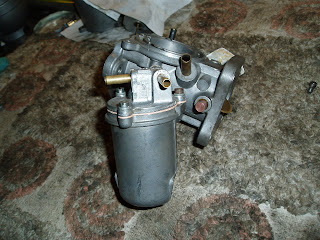
While I was fixing the self cancelling indicators and the horn, I needed easier access to the steering column. So the carburettors had to come off. They were very dirty, so I'd decided that it was time to get the toothbrush and the Gunk out and give them a scrub.
Most of this entry is going to be made up of photos as there is very little to expain about the SU carburettor. It is a superb piece of British engineering with something relatively simple yet able to accurately supply a fuel / air mixture to the engine.
A before shot....
Removing them from the inlet manifold, and a view of the inlet - looks pretty clean up there to me.
The carbs are joined together with this bracket in the picture below - the bracket holds the accelerator linkage (the long horizontal rod) which through the quadrant changes a 'pull' motion on the rod to a downward motion on the shorter vertical rod which then twists the short horizontal rod to pull the carburettor throttles open.
This bracket is not the genuine Standard Triumph part, it is a 'next best thing' that is sold by the TR suppliers. The original is unavailable (I've tried) and was unavailable when a previous owner converted the car from Strombergs to SUs. The bracket does have to be converted by drilling holes low down to accept the throttle return springs and to put them under the required tension to ensure that they do indeed return - I had to do this modification when I bought the car as it was impossible to properly tune the carburettors without it. While the bracket was off the car, I took the opportunity to cut off the slotted piece that you see on the left. A previous owner had opened the slot up, and bent it out of the way, but it is of no use on this vehicle, so had to go.
The real bracket should look like this.
It looks simple enough, I don't know why no-one has remanufactured it.
Here are the dismantling and rebuilding photos.


